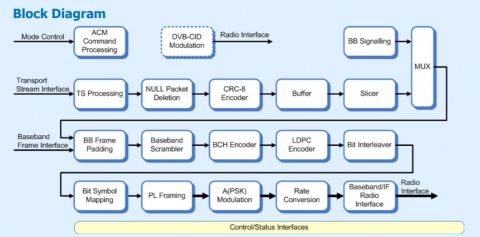
This is a DVB-S2X Modulator IP core with an integrated LDPC encoder has been designed specifically to address the requirements of the ETSI DVB-S2X forward-link satellite standard (EN 302 307), section-1 together with the section-2 extensions (DVB-S2X). The core can operate in CCM and VCM/ACM modes. This core provides all the necessary processing steps to modulate a single transport stream (or baseband frame) into a complex I/Q signal for input to pair DACs or an interpolating DAC device such as the AD9857(or AD9957). Optionally, the output can be selected as an IF to supply a signal DAC.
The active FEC code-rate and frame-size are defined by the mod_cod and type parameters associated with each TS packet (or input-frame) and are controlled through the external mode control ports, or optionally from a control register for CCM applications. The design has been optimized to provide excellent performance in FPGA devices. A description of the processing steps follows: TS Processing. The TS processing block performs rate adaptation functions in CCM Broadcast applications to ensure that variable transmission delays do not result in disturbances of time-critical services such as audio and video. Null packet deletion. The Null packet deletion block removes null TS packets from the input stream to maximize the capacity available for information services in VCM and ACM modes. The mechanism defined by DVB-S2X allows for complete restoration of the input stream when null packets are necessary to maintain a constant delay. CRC-8 Encoding. An 8-bit CRC is added to each outgoing TS packet and serves to allow packet-level error detection at the receiver. Slicer. The slicer block assembles each output BBFRAME from an integer number of TS packets. Padding may be used at the end of the BBFRAME if the number of bits is not exactly an integer number of TS packets. In VCM/ACM applications a new BBFRAME is initiated whenever the MOD COD or TYPE is modified. If this occurs before the end of an outgoing BBFRAME then the outgoing frame is padded. Baseband Signalling. The baseband signaling block inserts a fixed-length Baseband Header at the start of each BBFRAME. The structure of the Baseband Header is as described in EN 302 307. Baseband Scrambler. The baseband scrambler block performs the energy dispersal and transport multiplex adaptation using the DVB randomization polynomial 1+x14+x15. BCH, LDPC Encoders. These blocks systematically encode each frame and apply error correction. Bit Interleaver, Mapping. The bit interleaver block applies a block-based bit interleaving to the coded frame prior to symbol mapping. PL Framing. This block constructs the physical layer framing around the encoded frame data together with the physical-layer header. The PL Framing block is also responsible for intra-pilot insertion together with dummy-frame generation A(PSK) Modulation. This block generates the complex constellation points from the mapped symbol data. Rate Conversion. This block re-samples the complex samples output from the A(PSK) Modulation block at symbol-rate into complex samples at the core clock frequency. This provides an ultra-flexible clocking strategy allowing the core to operate from low symbol-rates up to a maximum of half the core clock frequency.
Baseband-to-IF. This block provides the option to mix the signal up to a higher IF as defined by a software register. This block may be removed using synthesis options if it is not required. Radio Interface. This block performs some final, register-selectable processing functions to optimize the output for the radio in the target application. For example, the data can be formatted to work with either twos-complement or offset-binary DAC devices. In addition, the data is formatted to suit the external vice that could take separate I/Q, multiplexed I/Q or a single IF output. Register Bank. The register bank provides a simple 32-bit interface for reading and writing registers within the modulator block. Full details of the registers within the modulator core are contained within the full datasheet.
